Author Topic: BE 646  (Read 210539 times)

dkp_cobra

  • Hero Member
  • *****
  • Posts: 931
    • View Profile
BE 646
« Reply #180 on: January 01, 2014, 13:43:06 »
quote:
Originally posted by French Frie
   
Hi Peter,
   
   Best wishes for this new year and let's hope that this Aceca will be on the road in 2014 ! Sorry to ask, but why didn't you weld the engine mounts directly on the chassis , rather than being bolted ?


   Hi Olivier,
   
   the car will be on the road this year, but probably not on it's own wheels ...
   
   I used this kind of clamped engine mounts because I didn't want big welding actions at the frame. This solution gives me (or more likely the person who will own this car when I am not on earth anymore) the possibility to change the engine without cutting off the mounts.
   
   It seems like a little bit complex solution but on the other hand it gave me the possibilty to play around with the right position of the engine wrt. place for headers, lower steering column, footbox and so on.

dkp_cobra

  • Hero Member
  • *****
  • Posts: 931
    • View Profile
BE 646
« Reply #181 on: January 10, 2014, 13:13:11 »
As I wrote I have to cut the footbox to get space for the clutch lever


   I only need 10 mm


   You can find a lot of things in the kitchen which help you


   Now, the clutch lever has enough space


   Time for something complete different. The moment of truth is coming. I take a look inside the main frame


   I found an interesting thing. Unfortunately, this quite robust but old borescope has analog technique and produces an S-VHS signal. The only S-VHS video grabber I found quickly works only with Windows XP and Vista but nearly kills my Windows 7  >:(.
   
   ... to be continued
« Last Edit: April 21, 2018, 12:58:01 by dkp_cobra »

BEX308

  • Newbie
  • *
  • Posts: 48
    • View Profile
BE 646
« Reply #182 on: January 15, 2014, 18:23:37 »
Peter,
   With a 289 installed I would encourage you to stiffen things up a bit. The video referenced in the link above is my car and I have complete details and pictures of how it was done; but Mikes description is very close. The modification effectively doubles the chassis stiffness but it is a lot of work. Both main tubes in 308 were bent in several places and required straightening prior to sleeving; 308 was raced and wrecked hard, so how many of the bends were from that I don't know. I can tell you that standing on the bare chassis before reinforcement caused a significant deflection and that the body was cracked in many places around the door openings. The tubes were driven all the way through without any problem; the worst part was the noise, and if Dorian's work is "bodging" as mentioned on this site I'd like to meet what you chaps call a real craftsman, the man is highly skilled and an artist to boot.
   In terms of handling; you'll never find a chassis designer who believes chassis flex should be part of suspension design. 'Nuff said.
   Let me know if I can help.
   Pete

Klassik Metall

  • Full Member
  • ***
  • Posts: 235
    • View Profile
BE 646
« Reply #183 on: January 16, 2014, 19:44:42 »
Hi Peter
   
   The main chassis tubes on Aceca's were made from 12 swg (2.8mm) thick steel the same gauge
   as that of the 289 cobras, so unless you have serious corrosion you should be OK with your new power plant.
   
   The Ace used 14swg (2.6mm) tube hence their more flexible nature.
   Also all the AC's with twin tube chassis tend to have a downward bow, due to the amount of
   welds that were made on only the top of the chassis tubes. Although the chassis would have been held in a jig
    for welding the arc welding originally used has very fast heating and rapid
    cooling which causes the weld area to shrink and pull considerably.
   
   I've found on several Aces that I've had in for repair that the chassis has quite a large bow
   end to end, yet the doors are still in perfect alignment with no closing of the door gaps.
   Therefor the main chassis tubes must have been bowed before the body subframe was
   completed. When I've tried to remove the bowing the door gaps open considerably and the
   door locks no longer align.
   
   Regards Luke.

dkp_cobra

  • Hero Member
  • *****
  • Posts: 931
    • View Profile
BE 646
« Reply #184 on: January 17, 2014, 18:51:55 »
Pete,
   
   I looked the video after you have mentioned it. It doesn't look like a funny work. My nightmare would be to have the new tube 1 m inserted and then nothing works anymore. No way to shift the new tube further in nor to get it out  :-\
   
   Luke,
   
   thank you for you comment. I think I have to open the tube at the front and back and clean them. As far as I could see I don't have rust problems in these tubes. In this case I think it is not necessary to insert new tubes. But it maybe a good idea as Mike mentioned to insert some kind of steel web. I think about four different possibilities:


   Solution 1 and 2 are quite simple since they would use standard parts (solution 2: a 50x50 mm square tube. The o.d. of the diagonal would be 71 mm but since the edges are rounded it should work). Solution 3 would be a T-profile. It is not so easy to find a 70 mm T-profile which is 3 mm strong. I think solution 4 would be the best but this is not a standard profile. This profile must be produced with a laser welder.
   
   What do you think?
« Last Edit: April 21, 2018, 12:59:04 by dkp_cobra »

BEX308

  • Newbie
  • *
  • Posts: 48
    • View Profile
BE 646
« Reply #185 on: January 19, 2014, 17:07:42 »
Peter,
   I know of at least one Ace that has used your option 1. It requires plug welding both edges every few inches to prevent buckling of the web to obtain the stiffness improvement. I looked at that approach and was not happy with the increase in stiffness obtained unless you go to a very heavy web. The moments of inertia (proportional to bending stiffness) for several possibilities are:
   Ace standard tube .083
   Aceca standard tube 1.034
   10 Ga web insertion   add  .24
   2.75 x .12 tube insertion add  .857
    Your option 2 would not be very effective in adding stifness for the amount of material used; it would be more effective with the square section rotated 45 degrees to provide 2 webs and 2 flanges in the loaded direction.
   I suspect options 3 and 4 are more trouble for less gain than either the square or tube insertion.
   Pete

dkp_cobra

  • Hero Member
  • *****
  • Posts: 931
    • View Profile
BE 646
« Reply #186 on: February 06, 2014, 16:17:40 »
I love the moment when parts arrive back from powder coating just before I can ruin them by assembling.
   
   The differential brackets with new rubber bushes


   In the background you can see the engine mounts not powder coated. There can only be one reason for that :o
   
   Small parts for the heating and fresh air system


   The mounting bracket for the upper steering column and the throttle pedal


   The boot lock and the lower part of the gas cap (nice constrast between the rechromed and the black powder coated part)


   and last but not least the hand brake lever. What a pity that it will be covered by leather.
   
« Last Edit: April 21, 2018, 12:59:25 by dkp_cobra »

dkp_cobra

  • Hero Member
  • *****
  • Posts: 931
    • View Profile
BE 646
« Reply #187 on: February 16, 2014, 09:38:15 »
I spent the last days removing the running gear.


   As expected it was a terrible job. The front lower wishbones seems to be as they wouldn't have been removed over the last 50 years.


   I had to cut most of the bolts, drilling and heating them before I was able to remove them. The sad rest of the bolts and rubber bushes.


   In the past the lower wishbones were repaired in a not quite professional way.
   
« Last Edit: April 21, 2018, 12:59:56 by dkp_cobra »

dkp_cobra

  • Hero Member
  • *****
  • Posts: 931
    • View Profile
BE 646
« Reply #188 on: February 19, 2014, 16:56:48 »
Let the dirt-days begin


   ... after the first day the air wasn't so good anymore ...
   
« Last Edit: April 21, 2018, 13:00:09 by dkp_cobra »

dkp_cobra

  • Hero Member
  • *****
  • Posts: 931
    • View Profile
BE 646
« Reply #189 on: February 22, 2014, 09:29:06 »
15 hours later. A lot of dirt


   and nearly 20 bristle discs (don't know the correct word)


   and the car has nearly no paint anymore. And the best news, no new big surprises [:)]


« Last Edit: April 21, 2018, 13:00:24 by dkp_cobra »

ace_mark

  • Newbie
  • *
  • Posts: 10
    • View Profile
BE 646
« Reply #190 on: February 23, 2014, 12:48:38 »
quote:
Originally posted by dkp_cobra
   
My Jag differential case is back from painting. Time for assembling.


   I bought a new 2.88 CWP (right in the picture) but it is much thicker than my current CWP (left). Is here a JAG expert? Is it possible that the new CWP is from a DANA diff.? The pinion has DANA stamped in.


   Anyway it does not fit into the case.


   Yes thats normal the Higher the Ratio is the Thicker the CWP is...
   is it the same ratio?

dkp_cobra

  • Hero Member
  • *****
  • Posts: 931
    • View Profile
BE 646
« Reply #191 on: February 23, 2014, 16:04:28 »
No, it wasn't the same ratio. The thicker was a 2.88 the smaller the original 3.07. The problem was that the 2.88 didn't fit into the case. Now, the diff is built up with an original 3.07 CWP.

dkp_cobra

  • Hero Member
  • *****
  • Posts: 931
    • View Profile
BE 646
« Reply #192 on: March 06, 2014, 10:56:21 »
Further 17 hours also the rest and the inside is paint-free.


   Now, I know why I got a replacement for the left rear wing although I need one for the other side:


   The car had an accident on the left rear wing but on the front part. The rear part was ok. So, a complete new left rear wing was bought but only the first 2/3 part was cut and welded in.
   
   One can see the edge of the replacement part (top) and the really bad weld seam with its holes:


   And it wasn't welded to the door sill but riveted and covered with 10 mm body filler:
   
« Last Edit: April 21, 2018, 13:00:53 by dkp_cobra »

dkp_cobra

  • Hero Member
  • *****
  • Posts: 931
    • View Profile
BE 646
« Reply #193 on: March 22, 2014, 16:26:55 »
Thank Barrie I have a new wall decoration
   
« Last Edit: April 21, 2018, 13:01:06 by dkp_cobra »

dkp_cobra

  • Hero Member
  • *****
  • Posts: 931
    • View Profile
BE 646
« Reply #194 on: April 04, 2014, 20:05:54 »
The today topic is "applied mathematics". I love it if I can use some of the maths stuff I learned in school to help real problems.
   
   Since the tubes of our cars are round we often have the same problem: cutting a hole into a tube in order to insert another tube:


   It would be nice if we can compute the dotted surface in order to print it, clue it onto the tube and make the cut along the edge.
   
   All you need is Pythagoras' theorem and trigonometric functions. Playing around with gnuplot I used this script:
   
   
Code: [Select]
set xzeroaxis
set yzeroaxis
set param
set samples 10000
r1 = 42.5
r2 = 38
plot [0:2*pi] sin(t)*r1,sgn(cos(t))*r2*asin(sqrt(r1**2-(sin(t)*r1)**2)/r2) notitle
   
   The result looks really strange


   but we have the special case that r1 > r2.
   
   Sticking it onto the tube doesn't make it better


   but when you turn the tube it really works


   I used the same technique to make an upper cut on the tube.


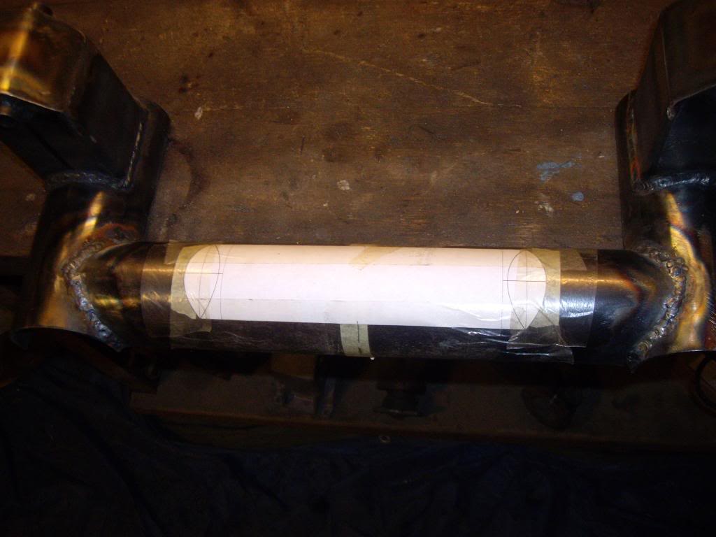
   This time the border should have an angle of 45°.


   ... and yes, this is a new version of the engine mount. It is the third version and I get more and more welding practice. The reason for the new version is that the engine mount should also enforce the stiffness of the main frame.
   
« Last Edit: April 21, 2018, 12:52:06 by dkp_cobra »