Author Topic: BE 646  (Read 210474 times)

dkp_cobra

  • Hero Member
  • *****
  • Posts: 931
    • View Profile
BE 646
« Reply #165 on: October 19, 2013, 17:04:00 »

Quote
Amazing, as usual, Peter !
   
   Ps: did you get a discount for the batch of level bars [;)] ?
   
   The level bars were in a package of three offered at a supermarket discounter for food  ;) Not professional but ok for this job.
« Last Edit: April 21, 2018, 13:02:20 by dkp_cobra »

dkp_cobra

  • Hero Member
  • *****
  • Posts: 931
    • View Profile
BE 646
« Reply #166 on: October 24, 2013, 15:40:17 »
Quote
HOLY INSTRUMENT CLUSTERS! It`s "Dashman"! The work you are doing is right on so many levels! [:)]
   Did you manage to do anything about the step in the side of the footwell?
   
   Nik,
   
   yes, I think I managed it. As usual, first converting a small hole into a big one


   Now, it's like the other side


   I have enough space for the steering column, the ignition plug and the shifter linkage


   but I still have to slot it the area of the clutch lever
   
« Last Edit: April 21, 2018, 13:03:16 by dkp_cobra »

nikbj68

  • Hero Member
  • *****
  • Posts: 2177
    • View Profile
BE 646
« Reply #167 on: October 24, 2013, 17:54:49 »
Oh that looks a lot more pleasing on the eye. It looks like the clutch won`t need to come too far into the footwell, but dare I suggest a 'dog-leg' lever? OK, I`ll shut up now!

dkp_cobra

  • Hero Member
  • *****
  • Posts: 931
    • View Profile
BE 646
« Reply #168 on: October 27, 2013, 14:33:24 »
My Jag differential case is back from painting. Time for assembling.


   I bought a new 2.88 CWP (right in the picture) but it is much thicker than my current CWP (left). Is here a JAG expert? Is it possible that the new CWP is from a DANA diff.? The pinion has DANA stamped in.


   Anyway it does not fit into the case.
« Last Edit: April 21, 2018, 13:03:43 by dkp_cobra »

dkp_cobra

  • Hero Member
  • *****
  • Posts: 931
    • View Profile
BE 646
« Reply #169 on: November 05, 2013, 16:49:42 »
Sometimes I am astonished about my false estimation how much time some sub-projects need to be finished. For example, I thought that the modification of the right header exhaust will take much more time than only an afternoon. But it wasn't. On the other side I thought that the overhauling of the rear view mirror is quite simple.


   The problems started with disassembling. The mirror broke. The first painting of the case was problematic and I had to redone it. While I screwed in the bolts after the second paint I slipped of with the screwdriver. So I had to repaint it again. The re-chromed frame came back after more than 4 mounth. And it was in a quite bad condition. The vents were nearly closed by the chrome and the opening of the frame was smaller than before because of too much chrome. While I tried to push the frame onto the case the mirror broke again because it was a little bit to big. Needless to say that the paint of the case got some ugly scratches.
   
   The next mirror was produced by technical drawing and not by copying the original broke mirror. Now, it fits really good into the case. The frame was re-chromed again with precise assignments which parts had to be ground. And of course the case was painted again. Was it the fourth time? I don't know anymore. Now, the result after five (5 !!!) mounth:


« Last Edit: April 21, 2018, 13:04:04 by dkp_cobra »

scud

  • Jr. Member
  • **
  • Posts: 50
    • View Profile
BE 646
« Reply #170 on: November 06, 2013, 11:48:13 »
Broken mirrors and bats at this time of year. You're a brave man not taking the month off!!

dkp_cobra

  • Hero Member
  • *****
  • Posts: 931
    • View Profile
BE 646
« Reply #171 on: November 08, 2013, 13:55:53 »
After the flop with the CWP from a big european dealer for vintage parts, I bought a differential at ebay.


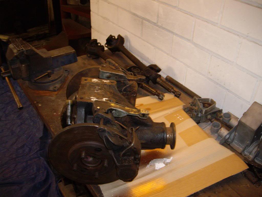
   The hardest part was carrying this fat baby into the basement. With brakes and rotors it has my weight [xx(]
   
   Opening it looks quite promissing. The wheels are wet


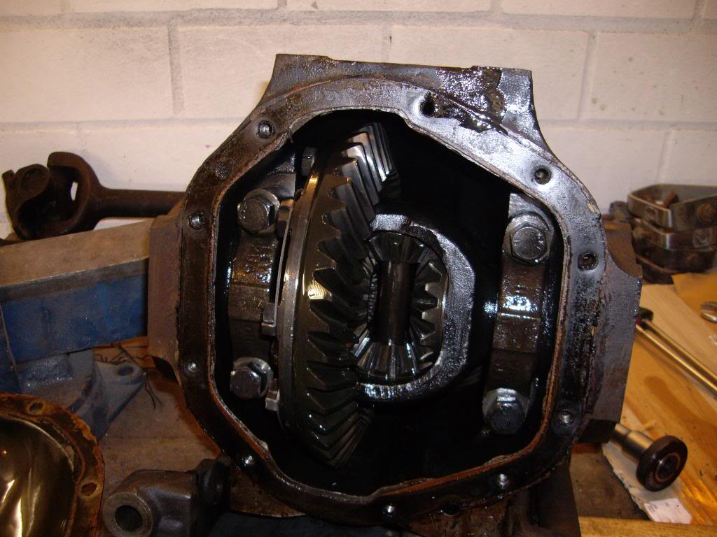
   and have the same size as my old wheels


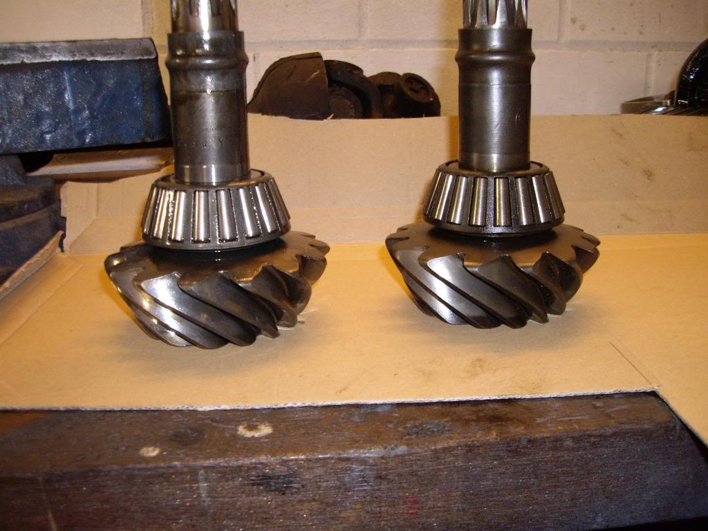
   Inspecting the new CWP it seems that this differential was overhauled and after that only some miles used. The wheels had still the paste you used to positioning the correct end. The brake rotors from Brembo have no signs of use.
   
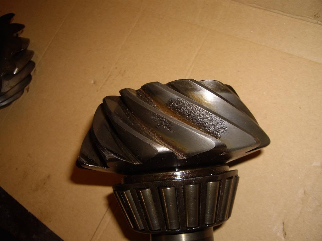
   So, it will end up with a 3.07:1 ratio. The problem with my old CWP was corrosion at the pinion


   Now, I have a nearly complete differential, rear brakes, new rear rotors, an overhauled Jaguar 4 speed transmission (was installed in the Aceca). I think this a half cat. Where do I get the other half [:I]
   
   Now, it is time to work on the footbox again. It would be nice if these parts could speak. What is the story behind this cut in the footbox:


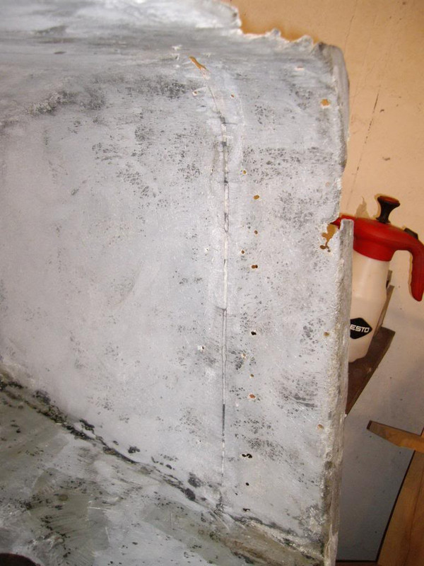
   And more interesting, it was repaired from outside:


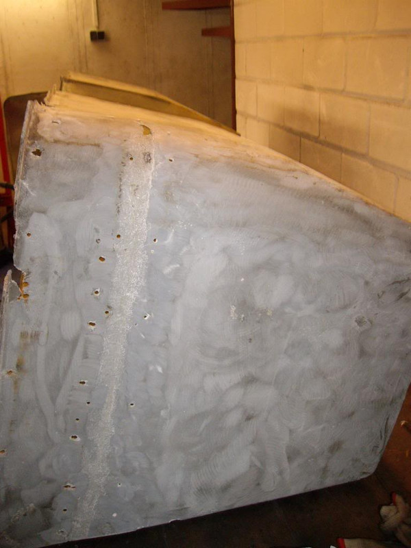
   You cannot reach this area when the footbox is installed. Well, not when the car has it's body.
   
   I had to plane some areas:
   
« Last Edit: April 21, 2018, 13:04:37 by dkp_cobra »

dkp_cobra

  • Hero Member
  • *****
  • Posts: 931
    • View Profile
BE 646
« Reply #172 on: December 06, 2013, 18:52:40 »
Working on the footbox became boring. I started with a new project: a mounting bracket for the upper steering column and the acceleration pedal.


   The bad look will disappear as soon as the parts are powder coated.


   A look from outside


   I got a little bit welding fever so I made these rings with weld nuts:


   They will fix the air vents on the foot box:
   
« Last Edit: April 21, 2018, 13:05:00 by dkp_cobra »

French Frie

  • Sr. Member
  • ****
  • Posts: 446
    • View Profile
BE 646
« Reply #173 on: December 07, 2013, 09:57:24 »
I wish I could be as skilled as you are, Peter ! For my knowledge: what is that "golden pen" seen in your pics ?

AC Ace Bristol

  • Hero Member
  • *****
  • Posts: 1510
    • View Profile
BE 646
« Reply #174 on: December 07, 2013, 17:44:37 »
.
   French Frie.
   
    The Gold Pen   you refer to is infact a Drift/Punch.
   
   When carrying out a restoration project it is surprising how many tools you need or adapt to assist in achieving your goal.
   If God had intended we restore cars he would have given us Xray vision, three hands,   more flexible joints, vice like asbestos grip etc...
   |There again, in some cases he would have given us a brain and taught us how to use it..
   
   Great project, good  creative skills and ingenuity which have been developed and honed as the project continues.
   
   The Aceca is so complex compared to our faithful Ace and|Cobra, Mind you it would have been much easier to have kept it as standard and not enhanced
   with 400HP of V8..
   There again, It would be a Boring world if we all had the same taste and same skills.
   
   Looking forward to seeing this Aceca out on the Highway and track.[;)]
   
   Keith..[:)]

dkp_cobra

  • Hero Member
  • *****
  • Posts: 931
    • View Profile
BE 646
« Reply #175 on: December 08, 2013, 09:55:59 »
Keith,
   
   V8 yes, but never 400HP. I think 180HP - 200HP is more than enough for that kind of car.
   
   Peter

mike harrison

  • Newbie
  • *
  • Posts: 10
    • View Profile
BE 646
« Reply #176 on: December 14, 2013, 09:53:35 »
Do you intend to change the rear upright and outer driveshaft layout? I think the standard components will not be able to cope with the extra power/torque.

dkp_cobra

  • Hero Member
  • *****
  • Posts: 931
    • View Profile
BE 646
« Reply #177 on: December 17, 2013, 09:16:01 »
quote:
Originally posted by mike harrison
   
Do you intend to change the rear upright and outer driveshaft layout? I think the standard components will not be able to cope with the extra power/torque.


   Mike,
   
   so far I have no plans to replace the rear uprights. After finishing the footbox the next  work will be the disassembling of the axles. Then I have a look inside the uprights and I will decide how to proceed.
   
   Peter

dkp_cobra

  • Hero Member
  • *****
  • Posts: 931
    • View Profile
BE 646
« Reply #178 on: January 01, 2014, 10:50:14 »
Last work of the last year: a transverse traverse for the engine mounting bracket to prevent it from rotation ...


   ... and little plates to keep it in position:


   The welding nuts at the upper mounting bracket for the upper steering shaft allows to change the steering wheel heights without the need of a helping hand to fix the nut in the engine bay:


   I guess I just managed to finish the engine/transmission mounting problems in the last year. See what will happen this year [?]
« Last Edit: April 21, 2018, 13:06:05 by dkp_cobra »

French Frie

  • Sr. Member
  • ****
  • Posts: 446
    • View Profile
BE 646
« Reply #179 on: January 01, 2014, 11:28:31 »
Hi Peter,
   
   Best wishes for this new year and let's hope that this Aceca will be on the road in 2014 ! Sorry to ask, but why didn't you weld the engine mounts directly on the chassis , rather than being bolted ?